A CAN Bus Primer Part 1: Introduction
An introduction to CAN bus, common applications and a dive into the interface itself.
 |
Introduction
In this article, we’ll take a look at the Controller Area Network (CAN) bus, a robust communication protocol designed for challenging electrical environments. We will explore what CAN bus is, discuss its interesting features and benefits, delve into the different modes of operation it supports, and highlight some of the common applications where it is widely used.
What Even Is CAN Bus?
CAN, or Controller Area Network, is a communications bus originally invented by Robert Bosch GmbH primarily for use in vehicles (Bosch being a large manufacturer of automotive electronic components) to save on copper wiring — the bus can have multiple connected devices that each have their own IO, rather than one central controller requiring a connection to each IO device.
CAN development efforts started in 1983, with an initial protocol release three years later at the Society of Automotive Engineers (SAE) conference held in Detroit, Michigan. Intel was the first company to release a CAN controller in 1987 shortly followed by Philips, with Mercedes-Benz being the first manufacturer to release a car (the W140 series) utilising the bus for control in 1991.
CAN Physical Layer
 |
CAN Bus and SAE J1939 Wiring Requirements And Trouble-Shooting - Copperhill
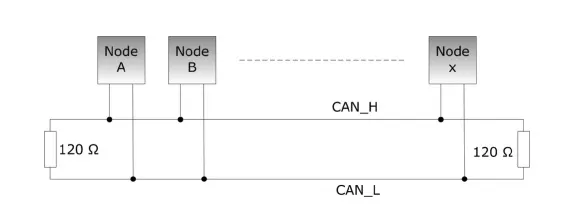
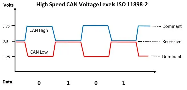
Similar to RS485, CAN utilises a differential multi-master serial bus. A termination resistor of 120 ohms is required at either end of the bus; this stops signal reflections and serves to return the bus to a recessive state (a binary one) where the voltage on CAN high is less than or equal to CAN low. A dominant state (binary zero) is expressed by CAN high being greater than CAN low, which is done by the transceiver actively driving the bus, compared to the termination resistors passively pulling the bus together. Active termination circuits are also described in the ISO11783 standard that enables hot-plugging of a CAN bus network.
Having these voltage levels means a CAN bus utilises differential wired AND logic, meaning that nodes that have a lower ID number take priority on the bus. CAN controllers are commonly employed — either as separate integrated circuits, or on-die circuits within microcontrollers — that handle bus arbitration; if two nodes transmit at the same time and one sees a zero on the bus, it will stop transmitting and retry after six-bit clocks have passed from the end of the message.
Various different bus topologies and termination types are possible, depending on the ISO standard implemented.
 |
ISO 11898-2, also known as high-speed CAN (with speeds of up to 1Mbps normally, or 5Mbps using CAN-FD) specifies a linear bus terminated at either end with 120 ohm resistors.
 |
The voltage levels are lower, with CANH being driven towards 3.5V and CANL towards 1.5V when a dominant (0) is being transmitted, with the two lines returning to a nominal differential voltage of 0V when the recessive (1) state is being transmitted — which is the idle state of the bus.
 |
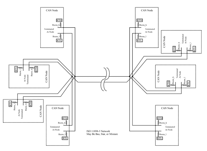
ISO 11898-3, or fault-tolerant CAN, can take multiple bus forms — including linear, star or multiple star buses all connected together and terminated at each node with a fraction of the total desired termination resistance. The bus runs at a much slower maximum speed of 125Kbps.
 |
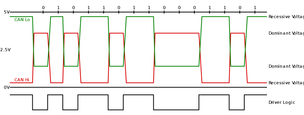
Much higher voltages are present on a fault-tolerant bus, with a dominant state transmitted by driving CANH towards the power supply voltage (typically 3.3 or 5V) with CANL being driven towards 0V. The recessive state is transmitted by letting the termination resistors pull CANH to 0V and CANL to 5V. Using higher voltage levels helps improve noise immunity as well as susceptibility to external faults that may induce voltages onto the bus.
Benefits Of a CAN Bus
Using a CAN bus can have benefits in many applications. One immediate benefit, particularly in automotive, is the reduced weight of wiring, whereby instead of having one centralised control unit with signal wires running to each sensor or actuator — modern cars have a great number of these, even down to things such as window regulators — only power and the two CAN bus conductors have to be run.
Additionally, putting all IO devices on a bus means that multiple control units can access the data. For example, an outside air temperature sensor could be accessed by an ECU, climate control unit and a driver display. Increasingly, the LIN (Local Interconnect Network) bus, which was also designed with automotive applications in mind, is complementing CAN bus by connecting non-critical systems such as air conditioning and infotainment.
Another benefit of utilising CAN bus is that the network automatically handles arbitration where two or more nodes attempt to talk at the same time. Due to the way the bus is wired, nodes with a lower ID number automatically get priority. Additionally, CAN controllers are required to automatically stop transmitting once a collision is detected and can generate a fault condition, with sufficient faults or collisions resulting in a “bus off” event where the controller gives up attempting to transmit data. It is then down to the microcontroller/CAN controller to decide how a bus off event should be handled.
The high differential voltages used on the bus, where a dominant or zero bit has a typical differential voltage of 2V or greater, whereas a recessive or one bit has a typical differential voltage < 0.5V, improves noise immunity. The use of differential signalling also helps as any common-mode noise will be induced onto both CANH and CANL signals, where only the difference in voltage levels is interpreted by the receivers.
CAN bus is also cheap and easy to implement in a lot of applications. The vast majority of modern microcontrollers feature CAN controllers built-in, with only the need for an external transceiver and ESD protection. In case a microcontroller does not feature an on-die controller, external ones that utilise an SPI interface are also widely available.
Applications of CAN Bus
The CAN bus is found across many industries, from automotive to aerospace, to agriculture and more.
Various higher-layer protocols are often run on top of CAN bus, some of the major ones include CANopen, ISO-TP, and NMEA2000.
CANopen
CANopen is an industrial automation protocol overseen by the CAN in Automation users group. This encompasses a communications protocol as well as device profiles for embedded devices used within automation, including an addressing scheme, several smaller communications protocols and an application layer that is defined by the device profile. Communications protocols include support for network management, monitoring of devices and communication between nodes — including a simple transport layer. Typically run over CAN (as the name implies), the protocol can also be run over other mediums such as Ethernet Powerlink and EtherCAT.
Basic profiles are set out in the CiA 301 standard, with more specialised profiles such as CiA 401 (for IO modules) and CiA 402 (for motion control) that build upon it.
ISO-TP
ISO-TP is a widely accepted international standard that sets out how to send data packets over a CAN bus. Typically, a CAN frame is limited to a maximum of eight bytes, but ISO-TP defines a packet standard that works within this eight-byte limitation.
This is done by segmenting a longer message into multiple CAN frames and including metadata that allows reassembly of the individual frames back into the original message at the receiving end. The maximum payload length is 232-1 bytes (4294967295 b) from the 2016 standard version; prior to which it was 4095 bytes.
The most common usage of ISO-TP is to transfer diagnostics messages in OBD-2 equipped vehicles utilising either KWP2000 or UDS communications protocols, but can also be widely found in other application-specific implementations.
NMEA 2000
NMEA 2000 is a marine-specific, plug-and-play communications standard used to connect sensors and display units on marine vessels. The typical communication speed of an NMEA 2000 bus is 250kbps and enables any sensor to talk to any display or other compatible device.
Protocol-wise, it is based upon SAE J1939 with specific messages applicable to the marine environment, which also enables J1939 devices to co-exist on the same CAN network. A standard connector, the 5-pin A-coded M12 screw connector, has been specified to ensure interoperability between different device vendors. The standard itself is administered by the US National Marine Electronics Association with only minimal information published; however, enthusiasts are making progress in discovering the device definitions through reverse engineering.
A certification process is offered by the NMEA which allows manufacturers to display a “NMEA 2000 Certified” logo, as well as ensuring that products can exchange data in a compatible way as well as coexisting on a network.
Conclusion
In this article, we’ve taken a look at what CAN bus is and its origins. We’ve explored the physical layer as well as various operating modes for fault tolerance and high speeds, plus the accompanying ISO standards that dictate how these networks should run.
Benefits including reduced wiring weight and complexity as well as unique features such as automatic arbitration mean that CAN bus is definitely worth considering using in a project where multiple devices need to sit on the same bus. We also took a look at some of the common applications where a CAN bus is utilised, demonstrating the depth and breadth of applications.
Jens

