
ESP32 S3 pullup down
When using input pins as digital input you can active a pullup or a pulldown resistor.
So with pullup activated input value will be high if nothing is attached to the pin (like a non pressed switch)
This is possible for all pins
from the tech manual ch 6 IO MUX link to manual
Note that the 45 GPIO pins are numbered from 0 21 and 26 48.
All these pins can be configured either as input or output.
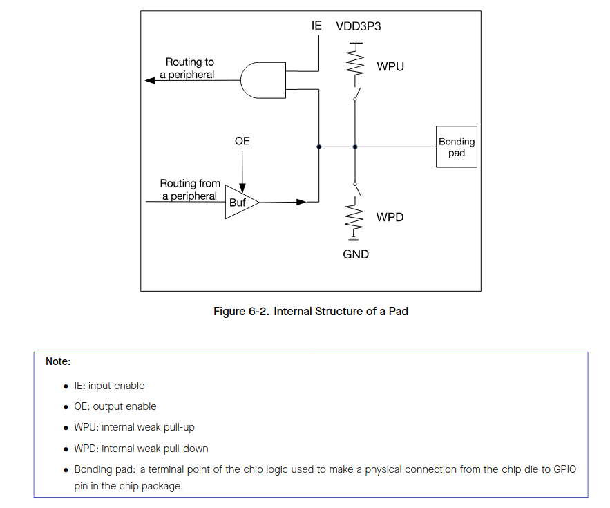
Figure 6-2(below) shows the internal structure of a pad,
which is an electrical interface between the chip logic and the GPIO pin.
The structure is applicable to all 45 GPIO pins
and can be controlled using IE, OE, WPU, and WPD signals
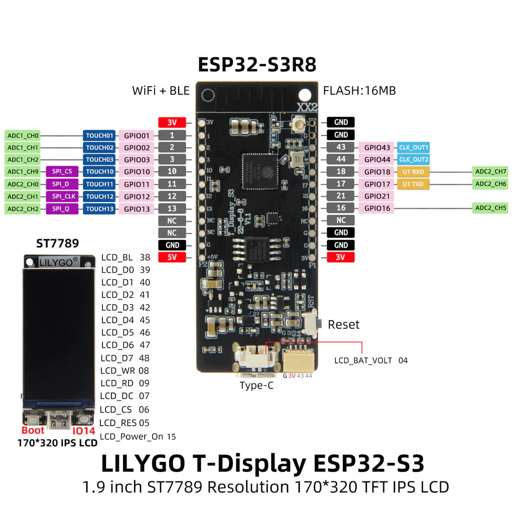
NOTE: Different boards with can have more or less digital pins available simply due to HW design. If pins are used for an onboard dispaly the pins might not be available externally.
So a slingshoot says you can use (on a S3 T-Display) 2,10,11,12,13,16,17,18,21,
see more below pin 14 is a button you can use as well
Outpud pad in the CPU (bonding pad is the physical pin)
 |
Arduino HOWTO input
pinMode(xx, INPUT)
pinMode(xx, INPUT_PULLUP)
pinMode(xx, INPUT_PULLDOWN)
Arduino OUTPUT
pinMode(xx,OUTPUT)
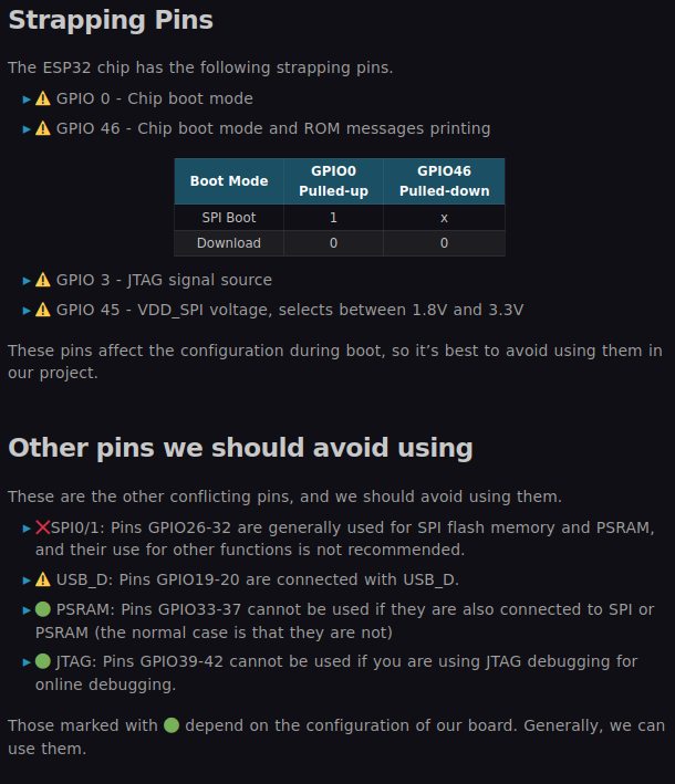
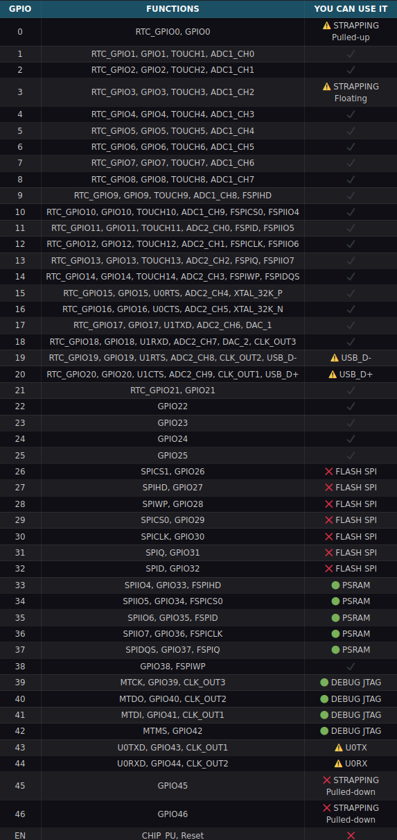
Beware
From https://www.luisllamas.es/en/which-pins-can-i-use-on-esp32-s3/
 |
 |
 |
references
tech manual - see section IO MUX
As long as you retain this notice you can do whatever you want with this stuff on these pages.
If we meet some day, and you think this stuff is worth it, you can buy me a beer in return :-)
(C) Jens Dalsgaard Nielsen
credit for license this goes to phk@FreeBSD.ORG
