Serial interface - cabling
Serial communication only define the serialised transmissoon of the bits in a byte.
See more at bit-tx.html
Old standard serial rs232-C cabling
unipolar cabling eg one line with bit stream and a ground level.
Levels mus be above +- 6V or so
logical 1 is -5V or lower
logical 0 is 5V or more
idle level is logical 1 eg -5V or lower
So interfacing to controllers with TTL level (see below) need a level converter.
RS232-C do also have additional signal lines like DTR, RTS etc
Rarely used today. TTL level serial is much more common.
See https://en.wikipedia.org/wiki/RS-232
TTL level serial communication
TTL level is defined as 0V and 5V. Naming comes from ancient TTL logic components.
Voltage and logic values
0V == logic 0
5V == logic 1
idle level is 5V
Idle level is 5V so it is possible to test for broken cabling
5.0V versus 3.3V or other “TTL” levels
Many controllers today is running at 3.3V so you might see 3.3V as logic 1.
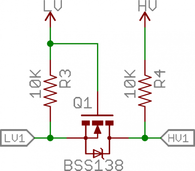
If you want to have controllers with different logic 1 levels (eg 3.3V, 5.0V,…) you might have to use level converters. Or more direct use level converters.
See
https://learn.sparkfun.com/tutorials/bi-directional-logic-level-converter-hookup-guide/all
https://arduinotech.dk/shop/i2c-logic-level-converter-module-5v-3-3v/
Link to schematics from Sparkfun
 |
LV1 Low level digital signal side
HV1 High level sigital signal side
LV Low side supply voltage
HV High side supply voltage
Lenght of cabling
TTL level unipolar cabling has some length issues due to typical low fanout of TTL serial ports and capacitive, resistive and inductive loads
In short
avoid cable length longer than 1-3 m.
if you go up in baudrate you have to go down in cable length
measure levels and shape of signals at receive end to evaluate if cables are to long
longer cables also mean higher level of noise collected up.
115200 is a high baudrate
if you go higher than 9600 or 19200 you are advised to look at signal quality with an oscilloscope at destination end at cable
A principial model for a cable
 |
So the initial square wave shaped bits will become filtered down the line and be lower in level and looks like passing a low pass filter.
input at left - output at right down the cable
It is out of scope of to go into further details
To be home safe lower baudrate as much as possible and do not have unnescessary long cables.
Transceiver based cabling to extend length
By use of proper transceivers like rs422 of rs485 much longer cables are possible.
https://en.wikipedia.org/wiki/RS-422 point to point
https://en.wikipedia.org/wiki/RS-485 multidrop
happy bit hacking to you :-)

